Abstract: A charging circuit for a full-contact non-contact electric vehicle with wireless feedback is presented. The primary coil of the non-contact charging circuit transmits electrical energy to the secondary coil on the chassis of the electric vehicle. The wireless feedback circuit wirelessly feeds back the sampled signal of the load voltage to the control end of the primary circuit in the non-contact charging circuit. The system automatically adjusts and changes the duty cycle of the full-bridge converter of the primary circuit to stabilize the output power at the set value. In addition, the circuit also has the functions of intelligent detection of battery power, automatic charging, floating charging and stop charging. Simulation and experiment prove the feasibility of the circuit.
Keywords: electric vehicle; non-contact power supply; wireless feedback
1 Introduction
The non-contact charging system (InducTIvelyCoupled Power Transfer, referred to as ICFT) used in electric vehicles enables the primary coil to transfer electrical energy to the secondary coil by electromagnetic induction. The secondary coil is installed on the chassis of the car, and the primary coil is installed under the ground of the parking space. When the electric vehicle is parked on the power supply coil device with a fixed parking space, the power receiving coil can receive electrical energy and charge the battery. Generally, electric vehicles can be charged within 3 to 6 hours.
Compared with the wired charging method, the non-contact charging system has the advantages of intelligent charging and no need to be on duty to charge the site; charging is not affected by weather and environment. Experiments show that the coupling coefficient of the non-contact charging system is low, usually between 0.13 and 0.2, and the voltage fluctuation across the load is large. Here is a non-contact power supply circuit with wireless feedback voltage regulation function. Without changing the coupling coefficient, the H-bridge duty cycle of the non-contact power supply circuit is adjusted to change the output power of the primary circuit to stabilize the output voltage .
2 Principle of non-contact power supply circuit
The schematic diagram of the non-contact circuit is shown in Figure 1. The circuit includes two parts: a non-contact power supply circuit and a wireless feedback circuit. The non-contact power supply circuit includes a primary circuit and a secondary circuit; the wireless feedback circuit includes a detection and transmission circuit and a reception and feedback trigger circuit, which can simultaneously realize intelligent control and voltage stabilization functions.
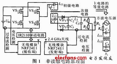
In Figure 1, the primary circuit is composed of power switch tubes VS1 ~ VS4 to form a full-bridge converter circuit. The PWM control chip SG3525 is used to control the push-pull circuit to generate control pulses, which alternately control the gates of VS1, VS4 and VS2, VS3, respectively AC current is generated at the terminal and the frequency is set to 30 kHz.
L11, L12 form a non-contact coupling converter. C1 and C4 are the compensation capacitors of the primary and secondary coils. The primary power supply, primary converter and primary coil L31 are installed under the ground; the secondary coil L12 and secondary converter are installed in the chassis of the car. Electrical isolation between primary and secondary.
VD1, VD2 and C2, C3 form a double voltage rectifier circuit, which supplies power to the load after being filtered by L2 and C5.
In the equivalent circuit of Fig. 1, the circuit before the H-bridge of the full-bridge converter can be regarded as a square wave voltage source, and its internal resistance RS is mainly the equivalent internal resistance of the power supply network billing meter. It can be seen that the necessary condition for RL to obtain the maximum transmission power is to make the primary and secondary circuits in resonance. According to this law, through theoretical calculations and Pspice simulation, L11 = 10μH, L12 = 112μH, C1 = 1 nF and C4 = 0.1 nF.
Introduction
SCOTECH manufactures a full range of oil immersed power transformers including generator step up transformer, substation step down transformer, mobile Substation Transformer and other different types, our maximum capacity and voltage is up to 300MVA 330KV, with the advanced design and thorough quality management system, we had become one of the most reliable Power Transformer manufacturers in China. we do not compromise on the quality, we ensure that each one of our delivered units has passed the most strictly testing and that makes us confidently to provide the longest quality warranty to our customers. We export our power transformers to all major global markets.
Scope of supply
SCOTECH`s oil immersed power transformers Including generator step up transformer, substation step down transformer, Mobile Substation Transformer and other different types.
Voltage level: 132KV, 230KV, 330KV.
Rating level: up to 300MVA
Standards
SCOTECH`s oil immersed power transformers are designed and manufactured in accordance with all major international standards (IEC, ANSI, UL, CSA etc.)
Why SCOTECH
Long history- Focus on transformer manufacturing since 1934.
Technical support – 134 engineers stand by for you 24/7.
Manufacturing-advanced production and testing equipment, strict QA system.
Perfect service-The complete customer service package (from quotation to energization).
Power Transformer
Power Transformer,Liquid Immersed Transformer,Step Up Power Transformer,High Voltage Transformer
Jiangshan Scotech Electrical Co.,Ltd , https://www.scotech.com